|

The following rendered wall modules (with texture mapping) will give you an idea of how
the Logmaker © log home software could be used to create 3D models and floor
plans. These are but some of the many variations that can be generated by adjusting a list of parameters. You can view a screen capture of the parameter list at the end, following these demonstration pictures.
Logmaker © has a 'smart' floor plan symbol that changes to reflect the length, width,
window & door position, module joins, curved ends, etc.. and other parameters
we adjust to suit 3D requirements (including sections and elevations). It has numerous snap points to facilitate rapid assembly of wall modules into a coherent design.
We can also 'stretch to fit' the log modules on the
floor plan without deforming the walls or moving the window position. See the floor plan
views below to get a better idea.
A new feature allows us to extract a dynamic log count as the plan evolves. See the sample report taken from an actual project after the parameter list at the bottom.
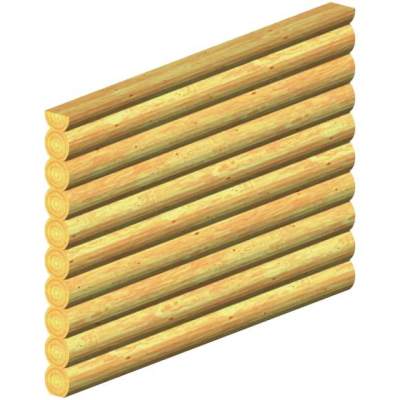
Picture 1
Simple stacked wall module - half-log on top, flat on first course bottom.
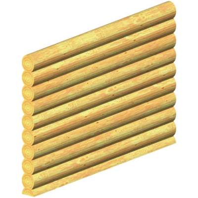
Picture 2
Same wall with half-log started on bottom.
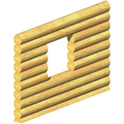
Picture 3
Wall with window opening, full logs above and below window frame.
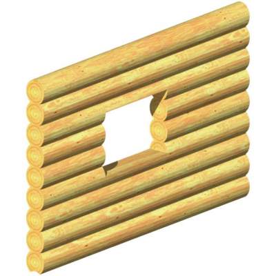
Picture 4
Wall with window opening, half logs above and below window frame, bottom log
coped for stacking.
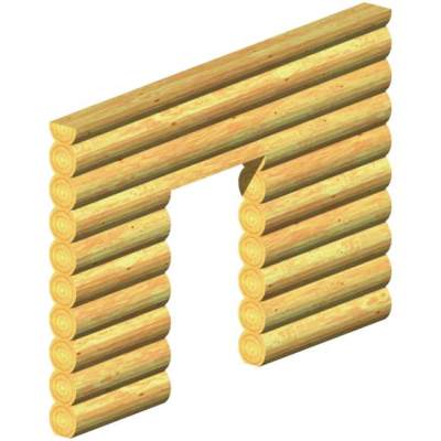
Picture 5
Wall with door opening, half log above door frame.
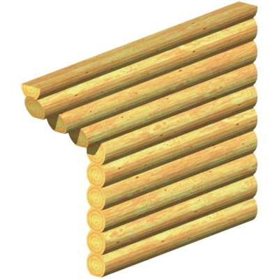
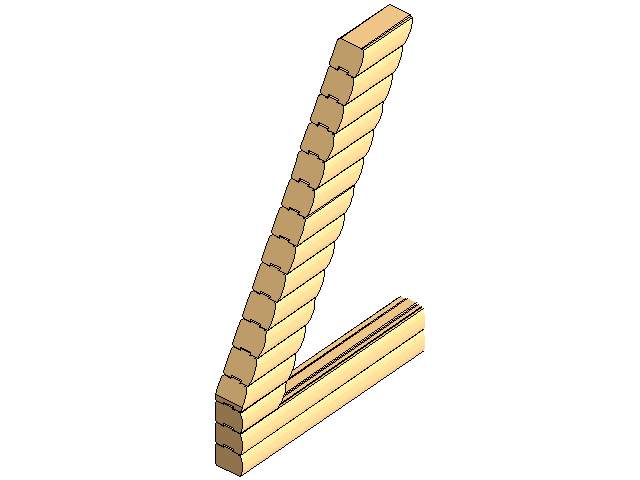
Picture 6
Wall with staggered end projection, 20 degree cut angle with flat bottom on staggered logs.
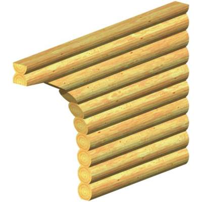
Picture 7
Wall with curved cut at end.
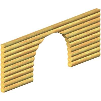
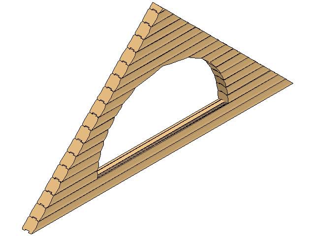
Picture 8
Wall cut with arch
The next four pictures were created in 'hidden line - shaded' mode. This is a quick, vector based mode similar to the hidden line mode below.
Note that the images have been converted to JPEG format for the purpose of
display via the internet, so the line definition suffers somewhat:
Picture 9: 'D log' Half-Round Window Opening with gable end cut
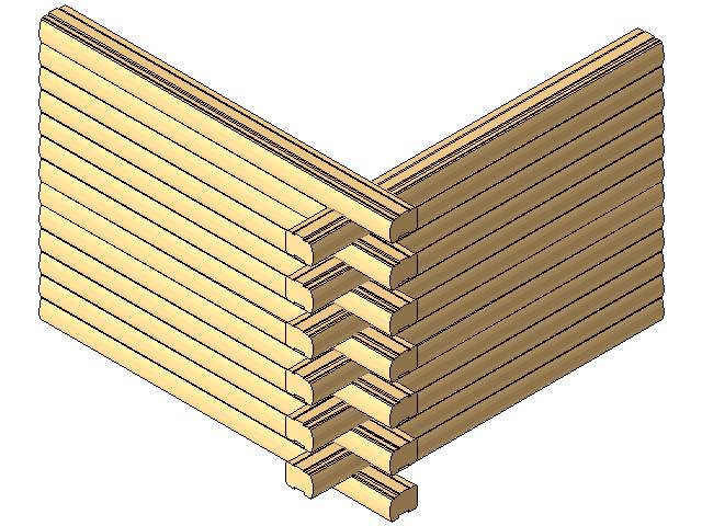
Picture 10: 'D log' Butt/Pass Corner-Exterior
Picture 11: 'D log' Rake Head Window Opening with gable end cut
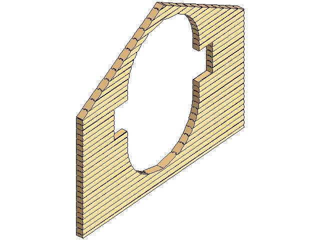
Picture 12: 'D log' Inverted Half-Round Window with gable end cut
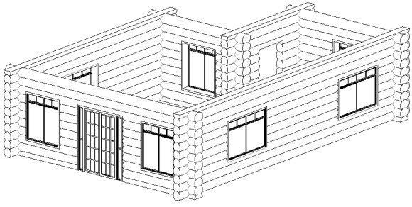
Picture 13 Here is an assembled 3D model in 'hidden line' mode. It is still a vector based image,
where as the rendered view (following) is a bitmap image. Hidden line
drawings are handy for faxing preliminary layouts, elevations, sections, or
construction details.
Although it appears slightly 'pixilated' over the Net,
these print and fax perfectly crisp, straight lines with no artifacts. There are a number of
other variations for this mode, color shading, wire-frame, etc.
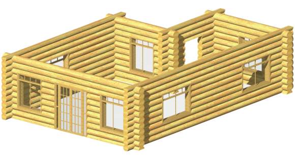
Picture 14 Assembled modules showing corner and general structure with window and door inserts.
Glass
transparency is set for a slight smoked effect, shadow casting has been
programmed for 9:00 AM, June 22, Vancouver B.C. No background picture has been
layered in, however this could be accomplished with a photograph, paint image,
virtual landscaping, or imported survey data.
A few spotlights added inside or outside the building could also provide some enhanced lighting effects
(via our VBS program, a wide range of lighting provides a rendered, adjustable 'lighting cone' which can actually be turned on and off).
Placing QuickTime VR cameras inside, we can produce an interactive walk-through of the house.
Exterior fly-bys are produced in a similar manner. These can be saved and
exported to video tape or digital media.
See the floor plan for this layout below.
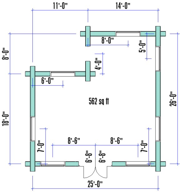
Floor Plan
This is the floor plan used to generate the 3D picture above. We elected to use a
color bitmap fill which prints out perfectly on our high-res color inkjet plotters, but
we could also choose to use a gray scale bitmap, vectorial hatch, or no fill at all. The Logmaker modules
develop all of the log design building components; Log - walls, tail sections,
siding, posts, beams, joists, rafters, purlins, ridge poles, stairs, railing,
decking, etc... If we stretch, move or modify the modules, the associative dimensioning, square footage, 3D view, elevations, sections and log count, update automatically.
Moving things around in elevation or section view and, again, everything else will update.
Note how the two log module symbols that make up the right hand wall join in a seamless manner, just as the 3D view does.
Developing a log wall layout plan, activating the 'AUTO ALTERNATE' mode,
will put the appropriate half-logs on the tops and bottoms of alternating right-angle walls.
Logmaker will also alternate butt and pass corners automatically in this mode.
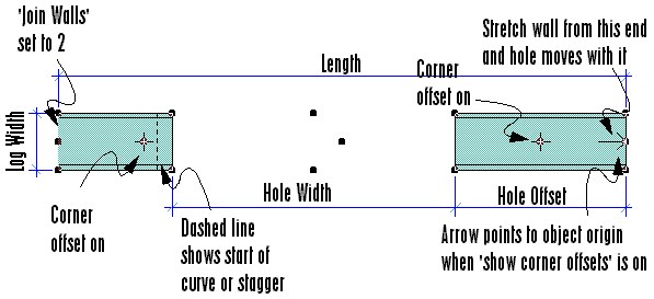
Floor Plan Symbol
This is a close-up of the floor plan symbol. It is in the 'selected' state, so you can see the snap nodes at all 4 corners,
center of ends, 4 corners of window & door hole, center of window & door hole, object
center, and corner offsets.
It is a 'smart' symbol in that it changes to reflect hole size, position, log joining,
etc.. If
we stretch it from the center node at the origin end, it will resize without changing the width of the wall and the opening will move with it.
Stretching it from the opposite end, the hole will stay put. Naturally, the 3D image (and everything else) would also be
updated automatically..
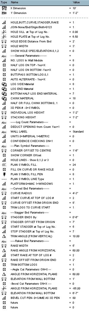
Parameter List
This is the 'heart' of the Logmaker system. We adjust these settings to
create or edit each desired log object, or to transfer the settings from one
object to another. Also, if dragging a copy (or copies), all the settings will remain with the new
modules.
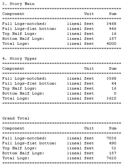
Log Count
We can call for a log count at any time during the design process via the 'calculate' menu.
Any wall category can be filtered out by adjusting the 'Wall Type' parameter.
All other components such as frame walls, concrete volume, gallons of paint, floor tile area, etc. will also be included
per our standard bill of materials reporting system.
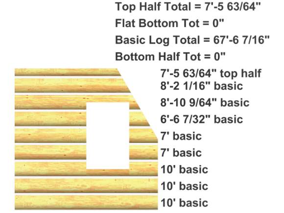
Log Count with visual Confidence Checking ON
If you're concerned about how Logmaker calculates the log count for different wall segments, we have
a feature called CONFIDENCE CHECKING.
We can select any module with this feature on, activate the 3D window, and Logmaker will display a log-by-log verification of the quantities generated by the log count. This example clearly shows the deduction of the angle cut as well as the treatment of window sills as full logs.
Further confirmation of the accuracy can be obtained simply by measuring the log lengths. As in this example, note that the accuracy can be set to display measurements as small as 1/64".
|  ©
©